 Jaydeep Chauhan
Hitech Engineering services delivers mechanical sheet metal design, drafting, 3D CAD modeling and Finite Element Analysis (FEA) services with accurate, timely and cost-effective solutions.
Source: https://www.hitechengineeringservices.com/detailed-engineering-design
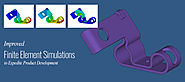
Finite Element Analysis (FEA) is an integral part of product development processes today. It has enabled engineers and designers to quickly evaluate the product design, determine stresses, deformation, useful life and failure characteristics within few numerical iterations.
Sheet metal parts are increasingly being developed by simulating the deformation process, in order to optimize the development time and improve the design quality. These simulations are often compared with modern optical measuring methods working on the principle of image processing to provide detailed information on 3D surface geometry, deformation as well as strain on formed sheet metal components.
FEA holds a promising future for product engineering design, and is being increasingly refined to improve the solver capabilities in predicting the behavior more accurately. With further developments in High Performance Computing (HPC), future finite element solvers are expected to become more reliable and eliminate the use of physical tests at many levels.
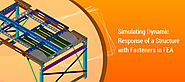
It is often difficult to simulate the dynamic response of structure consisting of number of screws or bolts, since it is expensive to represent every single hardware items in the simulation. It not only consumes time in setting up the simulation, but also eats up the computational time significantly. How then a design engineer can get the best answer from finite element analysis with less number of iterations?
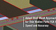
It is pretty much common to find companies trusting on solid-mesh simulations even when the geometry is thin-walled, like in the case of sheet metal or plastic parts. The common reason why analysts avoid using shell mesh for such cases is due to a common misconception that it will take too much time. Moreover, analysts also think that they do not require capturing the physics in detail, and hence ignore the rules of meshing thin walled parts
Finite Element Analysis (FEA) has brought numerous opportunities for product design engineers and manufacturers, and is now an integral part of product development process in industries like automotive, biomedical, aerospace, industrial equipment and heavy engineering. It fundamentally consists of three main phases: pre-processing, solution and post processing.
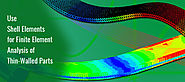
Performing finite element analyses using shell elements for thin-walled parts is often the best approach to save computational time. However, it is equally important to have good knowledge and experience with using shell elements to avoid erratic results from simulation. This is necessary because stresses in shell elements are captured differently as compared to solid ones.
Within the engineering community today, Finite Element Analysis (FEA) is widely considered as a tool to solve complex engineering problems. This is true to some extent, since FEA has allowed engineers to visualize complex physics within the product in matter of few hours, without relying on time consuming physical test trials.
A trend of constructing sky scrapers and grandiose bridges has become a measure to determine how technologically advanced the construction firm is. These firms constantly engage in erecting immense structures and bridges across large water mass, as a consequence to increase in population density and frequent long distance commutation.
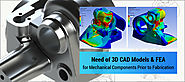
Rendered 3D CAD models which are well analyzed by FEA methods are must needed to enhance the output of products and study its performance and failure.
Design optimization essentially aims at improving product efficiency while making optimal utilization of resources. However, the optimization process is often time-consuming, especially while dealing with large data sets. Design engineers often face it challenging in delivering results due to the time utilized in analyzing large data sets. Analyzing and optimizing each data set manually, a common practice in iterative optimization approach consumes time in leaps.
Master the art of sheet metal design! This guide explores 10 expert tips for optimizing and improving your sheet metal drafting and modeling techniques, ensuring precision and efficiency in your designs. Learn effective strategies for documentation, grain direction, material selection, and more.

Jaydeep Chauhan is an Engineering Analyst at Hi-Tech Engineering Services and takes care of design analysis and optimization of mechanical products & eq...